Testbenches help you to verify that a design is correct. How do you create a simple testbench in Verilog?
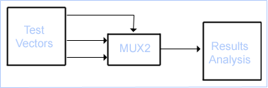
Let's take the exisiting MUX_2 example module and create a testbench for it. We can create a template for the testbench code simply by refering to the diagram above.
module MUX2TEST;  // No ports!
  ...
  initial
  // Stimulus
  ...

  MUX2 M (SEL, A, B, F);

  initial
  // Analysis
  ...

endmodule
Initial Statement
In this code fragment, the stimulus and response capture are going to be coded using a pair of initial blocks. An initial block can contain sequential statements that can be used to describe the behaviour of signals in a test bench.
In the Stimulus initial block, we need to generate waveform on the A, B and SEL inputs. Thus:
initial  // Stimulus
begin
  SEL = 0; A = 0; B = 0;
  #10 A = 1;
  #10 SEL = 1;
  #10 B = 1;
end
Once again, let's look at each line in turn.
SEL = 0; A = 0; B = 0;
This line contains three sequential statements. First of all, SEL is set to 0, then A, then B. All three are set to 0 at simulation time 0.
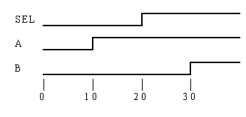
#10 A = 1;
In terms of simulation, the simulator now advances by 10 time units and then assigns 1 to A. Note that we are at simulation time = 10 time units, not 10 ns or 10 ps! Unless we direct the Verilog simulator otherwise, a Verilog simulation works in dimensionless time units.
#10 SEL = 1;
#10 B = 1;
These two lines are similar to the one above. 10 time units after A is set to 1, SEL is set to 1. Another 10 time units later (so we are now at simulation time = 30 time units), B is set to 1. The diagram below shows how the initial block has created a waveform sequence for the three signals.
We shall look at the use of the initial block to capture the MUX_2's response in the next section of the tutorial.
Prev Next