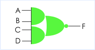
A design is described in Verilog using the concept of a module. A module can be conceptualised as consisting of two parts, the port declarations and the module body. The port declarations represent the external interface to the module. The module body represents the internal description of the module - its behaviour, its structure, or a mixture of both. Let's imagine we want to describe an and-or-invert (AOI) gate in Verilog.

Verilog: an AOI gate module
// Verilog code for AND-OR-INVERT gate
module AOI (input A, B, C, D, output F);
  assign F = ~((A & B) | (C & D));
endmodule
// end of Verilog code
OK, that's the code. Let's dissect it line by line...
Comments
// Verilog code for AND-OR-INVERT gate
Like all programming languages, Verilog supports comments. There are two types of comment in Verilog, line comments and block comments; we will look at line comments for now. Comments are not part of the Verilog design, but allow the user to make notes referring to the Verilog code, usually as an aid to understanding it. Here the comment is a “header” that tells us that the Verilog describes an AOI gate. It is no more than an aide de memoire in this case. A Verilog compiler will ignore this line of Verilog. Two forward slashes mark the start of a line comment, which is ignored by the Verilog compiler. A line comment can be on a separate line or at the end of a line of Verilog code, but in any case stops at the end of the line.
Module and Port declarations
module AOI (input A, B, C, D, output F);
The name of the module is just an arbitrary label invented by the user. It does not correspond to a name pre-defined in a Verilog component library. module is a Verilog keyword. This line defines the start of a new Verilog module definition. All of the input and output ports of the module must appear in parentheses after the module name. The ordering of ports is not important for the module definition per se, although it is conventional to specify input ports first.
A port may correspond to a pin on an IC, an edge connector on a board, or any logical channel of communication with a block of hardware. The port declarations include the names of the ports ( e.g., A, B ), and the direction that information is allowed to flow through the ports (input, output or inout).
Endmodule
endmodule
The module definition is terminated by the Verilog keyword endmodule.
Functionality
Well, that's the interface to the module taken care of, but what about its functionality?
assign F = ~((A & B) | (C & D));
In this module body, there is but one statement, and all the names referenced in this statement are in fact the ports of the design. Because all of the names used in the module body are declared in the module header and port declarations, there are no further declarations for internal elements required in the module body. assign is a Verilog keyword. It denotes a concurrent continuous assignment, which describes the functionality of the module. The concurrent assignment executes whenever one of the four ports A, B, C or D change value. The ~, & and | symbols represent the bit-wise not, and and or operators respectively, which are built in to the Verilog language. That's it! That's all there is to describing the functionality of an AOI gate in Verilog.
// end of Verilog code
Another Verilog comment, and that's the end of a Verilog description for an AOI gate.
Verilog 1995
The above example is written using Verilog-2001 syntax. Many people continue to use the 1995 syntax, which is still allowed in Verilog-2001. In Verilog-1995 the module header would look like this:
module AOI (A, B, C, D, F);
  input A, B, C, D;
  output F;
Note that the port names are listed after the module name, and declared as inputs and outputs in separate statements. The port declarations must repeat the names of the ports in the module header.
Next


