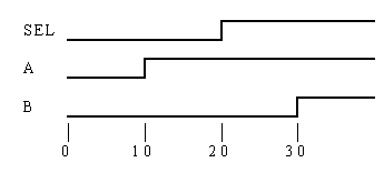
In the previous section, we looked at describing stimuli in Verilog to test our 2-input multiplexer. So next, we’ll look at how to capture the response of our device under test.

Remember from the module template that we are using initial blocks to code up the Stimulus and Response blocks.
module MUX2TEST;  // No ports!
  ...
  initial
  // Stimulus
  ...

  MUX2 M (SEL, A, B, F);

  initial
  // Analysis
  ...

endmodule
The Response initial block can be described very easily in Verilog as we can benefit from a built-in Verilog system task. Thus:
initial  // Response
  $monitor($time, , SEL, A, B, F);
Once again, let's look at each item in turn.
$monitor();
$monitor is a system task that is part of the Verilog language. Its mission in life is to print values to the screen. The values it prints are those corresponding to the arguments that you pass to the task when it is executed. The $monitor task is executed whenever any one of its arguments changes, with one or two notable exceptions.
$time
$time is a system function (as opposed to a system task). It returns the current simulation time. In the above example, $time is an argument to $monitor. However, $time changing does not cause $monitor to execute - $monitor is clever enough to know that you wouldn't really want to print to the screen the values of all of the arguments every time the simulation time changed.
, , ,
The space at position 2 in the argument list ensures that a space is printed to the screen after the value of $time each time $monitor is executed. This is a simple method of formatting the screen output.
SEL, A, B, F
Finally we come to the signal arguments themselves. Each time one of these signals changes value, $monitor will execute. When $monitor executes it will print all of the argument values to the screen, including $time. This is the output created by $monitor in our MUX2 testbench:
 0 0000
10 0101
20 1100
30 1111
This is simply a tabular listing of the waveforms that would be generated during simulation (if we had a waveform viewer, that is!).

It's amazing what you can learn from two lines of code, isn't it? We'll look at more elaborate output formatting soon.
Prev Next


